How should the power factor of single-phase be managed?

The low power factor of a single-phase circuit will lead to a decrease in equipment efficiency and an increase in line loss. To control the power factor, we need to analyze the causes and take targeted measures. The following are common control methods:

I. Common causes of low power factor
1. Mainly inductive loads
Equipment such as fluorescent lamps, motors, transformers, etc., need to consume reactive power during operation, resulting in a low power factor (usually less than 0.8).

2. Light load or no load
When the actual load of the equipment is far lower than the rated power (such as "a big horse pulling a small cart"), the proportion of reactive power increases and the power factor decreases.

3. Harmonic influence
Non-linear loads (such as inverters, switching power supplies, LED lights) generate harmonics, resulting in voltage and current waveform distortion and deterioration of the power factor.

II. Power factor control measures
1. Reactive compensation (the most direct and effective)
Through parallel capacitors or dynamic reactive compensation devices, capacitive reactive power is provided to offset the reactive demand of the inductive load and improve the power factor.
a. Fixed capacitor compensation
Applicable scenarios: occasions with stable load and small changes in reactive power demand (such as household single-phase motors and small office equipment).
Advantages: low cost, simple structure, and easy maintenance.
Disadvantages: unable to track load changes, may over-compensate (causing power factor to advance).
Installation method: connect the capacitor in parallel at both ends of the inductive load or in the distribution box, and pay attention to the matching of the capacitor rated voltage with the circuit (such as 220V single-phase system).

b. Dynamic reactive power compensation (such as thyristor switching capacitor)
Applicable scenarios: occasions with frequent load changes (such as welding machines, frequency conversion equipment).
Advantages: capacitors can be automatically switched according to real-time reactive power demand to avoid over-compensation.
Disadvantages: high cost and need to be equipped with a controller.

2. Choose high power factor equipment

a. Replace inefficient equipment: replace traditional equipment with energy-saving inductive loads (such as high power factor fluorescent lamps and permanent magnet synchronous motors).

For example: the power factor of ordinary fluorescent lamps is about 0.5, while energy-saving fluorescent lamps with electronic ballasts can reach more than 0.95.

b. Give priority to resistive or capacitive loads: such as electric heating equipment and LED lamps (high power factor models need to be selected to avoid harmonic products).

3. Reasonably match the load to avoid light load operation
a. Adjust the capacity of the equipment: select equipment with appropriate power according to the actual load to avoid "a big horse pulling a small cart".
Example: If the actual power of a single-phase motor is 0.5kW, select a model with a rated power of 0.75kW instead of 1.5kW.

b. Parallel operation or time-sharing use: For light-load equipment, multiple low-power devices can be connected in parallel to replace a single high-power device, or no-load operation can be avoided (such as turning off idle electrical appliances in time).

4. Harmonic control (for non-linear loads)
a. Install harmonic filters: Install LC filters or active power filters (APF) at the front end of non-linear loads (such as inverters and switching power supplies) to suppress harmonic currents and improve power factors.

b. Isolate non-linear loads: Power non-linear loads and inductive loads separately to avoid mutual influence of harmonics.

c. Select low-harmonic equipment: Give priority to electrical appliances that meet harmonic limit standards (such as IEC 61000-3-2), such as switching power supplies with PFC (power factor correction) circuits.

5. Optimize line layout and maintenance
a. Shorten power supply distance: Reduce line impedance and reduce reactive power loss in the line.

b. Regularly maintain equipment: Clean dust from motors, transformers and other equipment to ensure their operating efficiency and reduce reactive power loss caused by equipment aging.
LV capacitor bank
dynamic compensation SVG

Single-phase power factor control needs to be combined with load characteristics, with reactive compensation as the core, supplemented by equipment upgrades, harmonic control and load optimization. For ordinary users, priority is given to simple and easy capacitor compensation and replacement of high-efficiency equipment; for industrial or complex scenarios, professionally designed dynamic compensation and harmonic suppression solutions are required to achieve safe and economical governance effects.

Can Statcom control harmonics?

STATCOM (Static Synchronous Compensator) can help control harmonics, but its primary function is not harmonic filtering. Here's how it relates to harmonics:

1. Primary Role of STATCOM:

Reactive Power Compensation: STATCOM provides fast and dynamic reactive power support to regulate voltage and improve power system stability.

Voltage Stability: It helps maintain grid voltage by injecting or absorbing reactive power as needed.

2. Harmonic Impact of STATCOM:

Self-Generated Harmonics: STATCOMs use voltage-source converters (VSCs) with high-frequency switching (e.g., PWM), which can introduce high-frequency harmonics into the system.

Mitigation Through Design: Modern STATCOMs employ:

Multilevel Converters (e.g., cascaded H-bridge, MMC) to reduce harmonic distortion.

PWM Techniques (Sinusoidal PWM, Selective Harmonic Elimination) to minimize harmonics.

Filters (Passive/Active) to suppress residual harmonics.

3. Can STATCOM Actively Mitigate Harmonics?

Limited Direct Harmonic Control: STATCOMs are not primarily designed as harmonic filters, but some advanced configurations (like hybrid STATCOMs with active filtering) can help mitigate harmonics.

Combined Solutions: STATCOMs are often paired with passive filters or active power filters (APFs) to address harmonics effectively.

While a STATCOM alone is not a dedicated harmonic filter, properly designed STATCOMs (with multilevel converters and filters) can reduce harmonic generation. For strong harmonic mitigation, a combination of STATCOM + Active/Passive Filters is typically used.

Low voltage capacitor banks and filter banks

Both capacitor banks and filter banks are used in low voltage (LV) power systems for reactive power compensation and power quality improvement, but they serve different primary purposes.

1. Low Voltage Capacitor Banks

Purpose:

  • Reactive power compensation (power factor correction)
  • Voltage support (reduces line losses and improves efficiency)

Components:

  • Capacitors (fixed or switched)
  • Contactors/thyristor switches (for step control)
  • Protective devices (fuses, overload relays)
  • Controller (measures PF and switches steps)

Applications:

  • Industrial plants with inductive loads (motors, transformers)
  • Commercial buildings to avoid utility power factor penalties
  • Solar/Wind farms for grid compliance

Limitations:

  • Can amplify harmonics if system has existing distortion (risk of resonance).
  • Not designed for harmonic filtering (unless detuned).

2. Low Voltage Filter Banks

Purpose:

  • Harmonic filtering (reduces THD—Total Harmonic Distortion)
  • Reactive power compensation (secondary benefit)

Types:

  • Passive Filters:  LC circuits tuned to specific harmonics (e.g., 5th, 7th, 11th), mainly used for factories with VFDs, arc furnaces
  • Detuned Reactors + Capacitors Series reactors prevent resonance (e.g., 7% or 14% impedance), mainly used for systems with moderate harmonics
  • Active Power Filters (APF) Electronic compensation (injects opposite harmonics), mainly used for dynamic loads with varying harmonics

Applications:

  • Data centers (prevent harmonic overheating)
  • Hospitals (clean power for sensitive equipment)
  • Industrial facilities with VFDs, UPS systems, etc.
  • Advantages Over Plain Capacitor Banks:
  • Prevents harmonic resonance issues.
  • Reduces voltage distortion and equipment overheating.

3. When to Use Which?

  • Use a Capacitor Bank if:

Your main issue is low power factor (not harmonics).

Your system has low harmonic distortion (THD < 5%).

  • Use a Filter Bank (Passive/Active) if:

You have high harmonics (e.g., from VFDs, rectifiers).

You need both power factor correction and harmonic mitigation.

  • Hybrid Solution: Some installations use detuned capacitor banks (with reactors) to avoid resonance while still improving PF.


The Development Trend of Power Quality

1. Overview of the development of the power quality optimization and management equipment industry


Power quality refers to the nature and characteristics of the power provided to users by the power supply system, including voltage fluctuations, frequency stability, harmonic content, voltage flicker, power interruption and other aspects. Good power quality is the basis for ensuring the normal operation of power equipment and the power demand of users.

From the perspective of optimization and management equipment to solve power quality problems, it can be divided into power quality monitoring products, power quality management products, power quality software and services, etc.
In recent years, with the acceleration of my country's industrialization and urbanization process, and the popularization and application of various electronic equipment, the market demand for power quality optimization and management equipment has increased year by year. The market potential and industry prospects have attracted many companies to join. In this situation where competition is gradually intensifying, innovation ability and product quality have become important factors in corporate competition. At the same time, users' requirements for power quality are getting higher and higher, which means that technological innovation in the industry is imperative. For example, the development of high-precision power quality monitoring instruments and analysis software to accurately monitor and analyze problems in the power grid; upgrading various filters, compensation devices and voltage stabilizers used to eliminate harmonics, regulate voltage and improve power supply stability.
In terms of application areas, in addition to traditional industrial production fields such as metallurgy, chemical industry, communications, construction, and low-voltage distribution networks, with the rapid development of emerging fields such as wind power, photovoltaics and other renewable energy, a series of new power quality problems have emerged, which has also aggravated some long-standing power quality problems in the past. These fields have gradually become the key areas for the development of power quality products. At the same time, the power quality optimization and management equipment industry is gradually entering new life application scenarios such as residential areas and charging stations, and is more closely related to residents' lives.
Power Quality Problem

2. Application and market size of power quality optimization and management equipment in downstream


Power quality optimization and management equipment is mainly used to improve power quality problems in power systems to ensure the normal operation and high efficiency of equipment. It mainly includes voltage stabilizers, harmonic filters, flicker compensators and power quality analyzers. Among them, voltage stabilizers mainly adjust the output of transformers to maintain a stable voltage level to avoid voltage fluctuations causing equipment failures; harmonic filters are used to reduce the harmonic content in power systems, ensure the purity of power supply, and prevent harmonics from causing adverse effects on equipment; flicker compensators are used to control voltage flicker in power systems to ensure that equipment is supplied with stable power; power quality analyzers can monitor power quality parameters in real time in power systems, such as voltage, current, harmonics, etc., so as to analyze and identify power quality problems and provide operators with targeted improvement strategies.

Overall, with the continuous development of science and technology and the improvement of social informatization, the popularization of technologies such as the Internet of Things is gradually driving a significant increase in the demand for power quality optimization and management equipment. Power quality optimization and management equipment ensures the normal operation of production equipment and avoids production line interruptions caused by power quality problems by reducing problems such as harmonics and voltage fluctuations. According to statistics and forecast data, the global power quality optimization and management equipment market has a market value of approximately US$32.4 billion in 2021. It is estimated that by 2026, the global power quality optimization and management equipment market will reach US$46.1 billion, and the market size will continue to increase at a compound annual growth rate of approximately 7.3% per year. Among them, Asia-Pacific is the fastest growing region. As an important economy in the Asia-Pacific region, China plays an important role in this growth process. According to forecasts, by 2026, China's power quality optimization and management equipment market will continue to increase at a compound annual growth rate of 8.3%. This brings broad market opportunities for the power quality optimization and management equipment manufacturing industry.

3. Competition pattern of power quality optimization and management equipment market


With the development of the power system and the increasing prominence of power quality issues, the power quality optimization and management equipment industry has attracted many companies to enter the market. The demand for power quality optimization and management equipment is large, mainly concentrated in new energy, coal mines, steel and other factories and mines, and the market competition pattern is characterized by dispersion and low concentration.

Transformer and photovoltaic use at the same time

Analysis of the situation where the system load exceeds the transformer capacity configuration when the transformer and photovoltaic are used at the same time.

Phenomenon and cause
1. Power fluctuation superposition: The power generation power of the photovoltaic system is affected by factors such as light intensity and weather conditions, and fluctuates significantly. When there is sufficient sunlight during the day, the power generation power may increase significantly in a short period of time; while on cloudy days, cloudy days or in the morning and evening, the power drops sharply. If the system load itself is also in an unstable state at this time, such as the frequent start and stop of large equipment in industrial production, resulting in a large fluctuation in load power, the superposition of the two can easily cause the total system power to exceed the rated capacity of the transformer instantly. For example, in an industrial park equipped with a certain scale of photovoltaic power stations, when clouds suddenly appear in the afternoon to block the sun, the photovoltaic power drops sharply. At the same time, large equipment in several factories in the park starts at the same time, and the system load that was originally close to the upper limit of the transformer capacity is instantly overloaded, causing the transformer temperature to rise rapidly and emit abnormal sounds.

2. Unreasonable planning of photovoltaic installed capacity: When promoting photovoltaic projects, some regions have not fully combined the actual capacity of local transformers and future load growth trends for scientific planning. In order to pursue more photovoltaic power generation benefits, some users or enterprises blindly expand the scale of photovoltaic installations and connect a large number of photovoltaic equipment without in-depth evaluation of the original power supply system. For example, in some old communities, the transformer capacity has not been upgraded for many years. As residents' enthusiasm for photovoltaic power generation increases, they install photovoltaic panels on their roofs, and the total amount of installation far exceeds the transformer's tolerance, resulting in frequent instability in the community power supply, and even frequent tripping during peak power consumption in summer.

3. Insufficient load growth estimation: With economic development and the improvement of people's living standards, various types of electrical equipment are increasing. Whether it is the rise of emerging industries in the industrial field or the popularization of high-power electrical appliances in residents' lives, the demand for electricity continues to rise. If the future load growth estimation is too conservative in the planning stage of the transformer and photovoltaic system, and sufficient capacity margin is not reserved, when the actual load growth rate exceeds expectations, coupled with photovoltaic access, it is very easy to cause the system load to exceed the transformer capacity. For example, in recent years, new stores have been set up in a certain commercial area, and the catering, entertainment and other industries have brought a large amount of new electricity demand. At the same time, photovoltaic systems have been installed on the roofs of some buildings in the area. The capacity of the transformer originally designed can no longer meet the total demand of the existing and new loads and photovoltaic access, and power supply tension often occurs.

Impact
1. Transformer overheating or even damage: When the system load exceeds the transformer capacity, the current of the transformer winding increases. According to Joule's law Q=I2Rt (where Q is heat, I is current, R is resistance, and t is time), the heat generated by the winding increases significantly. Being in this overloaded and heated state for a long time will accelerate the aging of the transformer insulation material and reduce the insulation performance. In severe cases, it may cause a short circuit in the winding, causing damage to the transformer and leading to a large-scale power outage. For example, in a rural distribution network connected to a photovoltaic power station, due to the large number of electrical equipment such as air conditioners turned on during the high temperature period in summer, coupled with the instability of photovoltaic power generation, the transformer was overloaded for a long time, and the insulation material eventually burned out, and the transformer was completely damaged, affecting the normal power supply of many surrounding villages.

2. Power quality degradation: On the one hand, overload operation will reduce the transformer output voltage, resulting in excessive voltage deviation. For some equipment with high requirements for voltage stability, such as precision electronic equipment, industrial automation production lines, etc., low voltage may cause the equipment to fail to work properly or even damage the equipment. On the other hand, the harmonics generated by the photovoltaic system and the load interact when the transformer is overloaded, which may further amplify the harmonic content, affect the power quality of the power grid, and interfere with the normal operation of other electrical equipment, such as causing additional vibration and noise in the motor, reducing the service life of the equipment. For example, in a factory power grid with both photovoltaic access and a large number of industrial equipment, the voltage deviation reached ±10% because the system load exceeded the transformer capacity, causing multiple imported precision processing equipment in the factory to frequently alarm and shut down, and harmonic pollution caused some lighting fixtures to flicker.

3. Reduced power supply reliability: The system load exceeds the transformer capacity configuration, which will increase the risk of power outages. Once the transformer stops operating due to an overload fault, it will directly cause a power outage in the area it supplies power to, affecting residents' lives, industrial production and commercial operations. Even if the transformer is not completely damaged, frequent overload warnings and protection actions will cause intermittent power supply, seriously affecting power supply reliability. For example, in an old neighborhood of a city, due to insufficient transformer capacity and excessive photovoltaic access, there are multiple power outages every week during the peak period of summer electricity consumption, which brings great inconvenience to residents' daily life and also causes economic losses to commercial activities in the neighborhood.

Countermeasures
1. Reasonable planning and capacity expansion: Conduct a comprehensive survey of the existing power grid and load conditions, combine the distribution of photovoltaic resources with future development plans, use big data analysis and load forecasting models to accurately predict the load growth trend. On this basis, scientifically determine the scale of photovoltaic access according to the transformer load rate and remaining capacity. For areas with great load growth potential and rich photovoltaic resources, if the existing transformer capacity cannot meet the demand, the transformer capacity should be expanded and upgraded in time. For example, during the planning stage of a new industrial park, through detailed load research and forecasting, it is expected that the load will increase by 50% in the next 3-5 years. At the same time, considering that a large number of roofs in the park can be used to install photovoltaics, it is finally decided to upgrade the original 1000kVA transformer to 2000kVA, and reasonably plan 500kW photovoltaic access capacity to ensure the stability and sustainability of power supply.

2. Install adjustment equipment: Install a maximum power point tracking (MPPT) device in the photovoltaic system to adjust the working state of the photovoltaic panel in real time so that it always outputs at maximum power and reduces power fluctuations caused by changes in light. At the same time, configure a dynamic reactive power compensation device (SVG) to compensate in real time according to the reactive power demand of the system, stabilize the voltage, improve the power factor, and reduce the load pressure of the transformer. For example, in a rural power grid connected to a 1MW photovoltaic power station, after installing MPPT and SVG devices, the fluctuation range of photovoltaic power was reduced by 30%, and the output voltage deviation of the transformer was controlled within ±5%, which effectively improved the power quality and transformer operating conditions.
SVG Wall-mounted module
SVG Cabinet

3. Optimize operation management: Establish a smart grid monitoring system to monitor the operating status of transformers, photovoltaic systems and loads in real time, including parameters such as voltage, current, and power. Through data analysis, predict possible overload risks in advance and take timely adjustment measures, such as adjusting the output power of photovoltaic inverters and guiding users to use electricity at off-peak times. For example, a city's smart grid monitoring center uses big data analysis technology to conduct real-time monitoring and analysis of transformer and photovoltaic system operating data throughout the city. When it finds that the transformer load rate in a certain area is close to 80% and has a trend of continuing to rise, it sends peak-shifting electricity consumption reminders to large commercial users in the area through a mobile phone APP, successfully avoiding the occurrence of transformer overload.

Introduction to Digital Tearing Tester

The Digital Tearing Tester is a precision instrument used to measure the tear strength of various materials. It uses advanced electronic technology and precise sensors to accurately measure the tear strength of various materials. It is widely used in many industries such as textiles, leather, plastics, paper, etc. It aims to accurately quantify the resistance of materials under tearing force, and provide key data support for product quality control, material performance research and production process optimization.


Fabric Tearing Testing machine has a wide range of applications.

  1. In the textile industry, it can test the tear resistance of textiles and non-woven fabrics to provide data support for product durability.
  2. In the packaging industry, it can be used to test the tear resistance of packaging materials such as plastic film, paper, and cardboard to ensure that the packaging is not easily damaged during transportation and use, thereby protecting product safety.
  3. In the rubber, plastic, leather and other industries, it also plays an important role in helping companies control product quality and improve product performance.


The Digital Elmendorf Tearing Tester has many advantages, such as color touch screen display, pneumatic clamping of samples, automatic shearing incision, automatic release of pendulum, etc. The instrument can automatically detect and analyze data, and can be configured with computer software for online testing. This instrument has the characteristics of high test accuracy, high degree of automation, powerful functions, reliable performance, and simple operation.


Elmendorf Tearing Strength Tester, with its high precision, easy operation and multi-function, has become a powerful assistant for material tearing performance testing in many industries, making important contributions to improving product quality and promoting industry development.


AVENO recommended product:


Digital Tearing Tester AG11-3

Digital Tearing Tester


Any demand can be referred to us!

Sales Dept Tel: +86 15280858852

Email: sales@avenotester.com

Skype: sales@avenotester.com

Web: www.avenotester.com


The color guardian of the textile industry

Gas Fume Chamber plays an indispensable role in the production and quality control of textiles. As people's requirements for textile quality continue to increase, the color fastness of textiles has become a key quality indicator. Gas Fume Chamber is a member of the guardian of textile quality assurance. So what is Gas Fume Chamber?


Gas Fume Chamber is mainly used to test the color change of textiles when they are exposed to atmospheric nitrogen oxides produced by gas combustion. It simulates the specific gas atmosphere that textiles may encounter in real environments to test their color stability.


How the Gas Fume Tester Works

The textile sample and the control standard sample are placed in the gas smoke at the same time, and the test ends when the color of the control standard sample changes to the color equivalent to the fading standard. The color change of the sample is evaluated using a gray sample card. If no color change of the sample is observed after one test cycle, the test cycle can be continued for a specified number of times or the number of test cycles required to produce the specified color change of the sample.


Through the Gas Fume Chamber test, manufacturers can understand in advance the color changes of textiles in a specific gas environment, so as to take corresponding measures to improve the production process, select suitable dyes and auxiliaries, so as to improve the color fastness of textiles and meet consumers' demand for high-quality textiles.


Standards Of Lab Gas Fume Chamber

AATCC 23, ISO 105 G02, BS EN ISO 105-G02


Although Gas Fume Chamber is only a small part of textile testing instruments, it plays a huge role in the textile industry. It is like a color guardian elf, silently guarding the color quality of textiles and bringing us more beautiful and durable textiles.


AVENO recommended product:

Gas Fume Chamber AG43

Gas Fume Chamber

Any demand can be referred to us!

Sales Dept Tel: +86 15280858852

Email: sales@avenotester.com

Skype: sales@avenotester.com

Web: www.avenotester.com

Time Accelerator--UV Accelerated Weathering Tester

UV Accelerated Weathering Tester, like a "time accelerator", can give us insight into the aging test results of materials in long-term outdoor environments in a short period of time.


The working principle of UV testing equipment simulates factors such as sunlight, rain, and dew in the natural environment. It uses special fluorescent UV lamps to accurately simulate ultraviolet radiation in sunlight, allowing the material to be exposed to high-intensity UV radiation. At the same time, through the condensation humidity and water spray system, it simulates the erosion of dew and rain on the material. Under the alternating cycle of UV light, controlled humidity and high temperature environment, the material undergoes the test of long-term exposure outdoors. The aging phenomenon that may take months or even years to appear may appear within a few days or weeks. It is widely used in the selection of new materials, the improvement of existing materials, and the evaluation of changes in material formulations.


Advantages of UV Aging Testing Machine

1. Easy to operate: The device is equipped with an advanced control system and a simple user interface.

2. Accurate simulation: It can accurately simulate factors such as ultraviolet rays, temperature, humidity, etc. in the natural environment, making the test results more reliable and repeatable.

3. Efficient testing: Compared with long-term aging tests of materials in the natural environment, the use of UV Accelerated Weathering Tester greatly shortens the test cycle, saving time and cost.


Many companies have achieved remarkable results with the help of UV Accelerated Weathering Tester. As an important tool for material aging testing, it provides strong support for product quality improvement and technological innovation in various industries. It allows us to understand the performance changes of materials in a long-term natural environment in a short period of time, so as to take measures in advance to optimize product design and production processes.


AVENO recommended product:

UV Accelerated Weathering Tester AG19

UV Accelerated Weathering Tester

Any demand can be referred to us!

Sales Dept Tel: +86 15280858852

Email: sales@avenotester.com

Skype: sales@avenotester.com

Web: www.avenotester.com


What is the Solution of IS 17636-2021 Bunk Beds


What is the Solution of IS 17636-2021 Bunk Beds

Bunk beds are widely used products in residential homes, hostels, and dormitories due to the space-saving design of beds. Bunk beds are an important segment in the furniture industry; hence, the safety and sturdiness of the bunk bed are very crucial. The standard aims to ensure that bunk beds are safe, durable, and comfortable for use, particularly for children and adults, by specifying the necessary construction practices, material quality, and safety features.


IS 17636-2021 Bunk Beds


It ensures that bunk beds meet required safety standards, minimizing accidents and guaranteeing long-term reliability. and thus minimize the occurrence of accidents, hence ensuring reliability in the long run.

Why IS 17636-2021 Is Important for Bunk Beds


The IS 17636-2021 standard is India’s official guide for how bunk beds should be made. It covers all the key points that make a bunk bed safe and fit to use.

This standard checks for things like:
  • Load-bearing strength: Can the bed hold the right weight?
  • Stability: Will it tip over if a child climbs up?
  • Sharp edges: Are all edges smooth and safe?
  • Guardrails: Are the side rails tall enough to stop someone from falling?
  • Ladder design: Is the ladder safe and easy to climb?
These rules are in place so that the beds do not break, shake, or hurt anyone. The standard is written in a simple way so that every builder or importer can follow it clearly.

Scope of IS 17636-2021

The Indian Standard IS 17636-2021 covers bunk beds’ safety and performance requirements, including:

  • Strength, stability, and durability for both domestic and non-domestic use.
  • Safety barriers for top beds to prevent falls.
  • Design specifications, including required gaps, bed base support, and ladder stability.
  • Material testing for surface finishes, load-bearing capacity, and impact resistance.

What is The Solution of IS 17636-2021 Bunk Beds

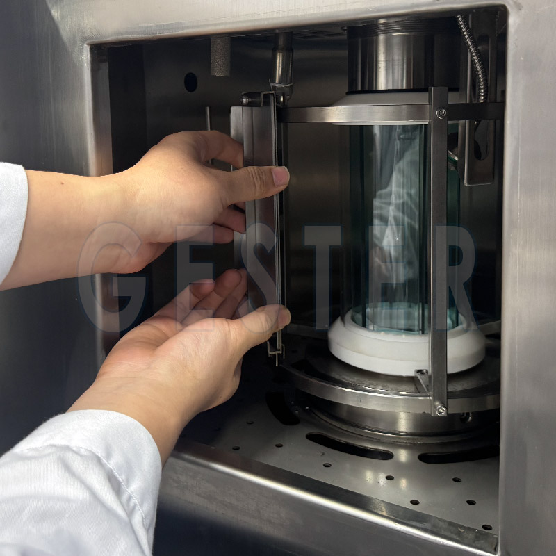
GESTER's Furniture Universal Testing Machine PLC control GT-LA10D conforms to IS 17636-2021.
Test Performance:
  1. Static Load of Safety Barriers
  2. Upwards and Downwards Static Load on Bed Base
  3. Impact Load of Bed Base
  4. Durability Test on Bed Base
  5. Durabllity Test of Frame and Fastenings
  6. Attachment and Deffection
  7. Vertical Static Load on Treads
  8. Durability of Treads
  9. STABILITY TEST
  10. Fastening of Upper Bed to Lower Bed
Furniture Universal Testing Machine PLC control GT-LA10D

Furniture Universal Testing Machine PLC control GT-LA10D Feature


  • 1. The Furniture Testing Machine adopts frame structure design. The frame is made of high quality industrial aluminum, beautiful and generous.
  • 2.Up to 8 sets of loading cylinder installed, 5 sets in horizontal cylinders on each of the four sides, 2 sets of vertical cylinder and 1set of impact cylinder on top frame. All cylinders can be adjusted up and down, frontward and backward to cover all mounting surfaces. The 8 sets of cylinders can execute joint or independent operation.
  • 3. The bottom fixed block is free to adjust the position to accommodate different specifications of the sample.
  • 4. PLC +15 inch color touch screen to control the actions of the machine; the operation is intuitive and simple.
  • 5. GESTER independent research and development unique design, adopting SMC electrical proportional valve control+cylinder drive mode way to greatly meet the international standards of force accuracy and test speed double requirements; high precision force sensor sense the force value immediately; each load group adjusts the control individually; the loading force is stable and reliable.
  • 6. Removable loading pad, can easily change the different loading pad to meet the different test requirements.

Bunk beds are more than just a place to sleep. They must be safe, stable, and child-friendly. GESTER' Furniture Universal Testing Machine, Solution of IS 17636-2021 Bunk Beds, which significantly reduces the risk of accidents due to structural defects or material problems and enhances consumer trust.


PE film roll bag water packaging machine operation and maintenance manual

In today's fast-paced production environment, PE film roll bag water packaging machine has become a powerful assistant for many companies to improve production efficiency and ensure product quality. The following will focus on the production process, operation manual and simple maintenance tips of this machine.

Equipment production process

Liquid filling: The liquid filling system of the PE film roll bag water packaging machine is a key part. Water or other liquid products can usually be injected into the PE film roll bag by gravity drop or pumping.

PE film roll supply: juice packaging machine is equipped with a special PE film roll supply device. The PE film roll material is placed in rolls. During the transmission process, the system will maintain a constant tension to avoid damage caused by excessive relaxation or tension of the film roll, ensuring that the film roll smoothly enters the bag making link, laying a good foundation for subsequent operations.

Bag making and sealing: When the PE film roll is delivered to the designated position, the bag making and sealing systems of the packaging machine begin to work together. First, the machine will cut the bottom of the roll film according to the preset size to form independent bag blanks. Then, the bag blank is turned into a three-dimensional bag through the middle seal. Then fill the liquid, and finally, use heat sealing technology to seal the bag mouth.

Operation Manual

Preparation before starting the machine: The operator needs to conduct a comprehensive inspection of the equipment, including whether all components are installed in place, whether the connection is firm, whether the power supply and air source are normal, etc. At the same time, according to the production plan, prepare the corresponding PE roll film materials and liquid products, and install the roll film correctly on the supply device to ensure that it can be unfolded smoothly. Check whether the parameter settings of the control system, such as filling volume, packaging speed, etc., meet the current production requirements, and make timely adjustments if there are deviations.

Start the equipment: After checking that everything is correct, press the start button and the packaging machine starts running. In the initial stage, the operator should closely observe the operating status of the equipment and pay attention to whether there are abnormal sounds, vibrations or liquid leakage. If there is any abnormality, the machine should be stopped immediately to investigate the cause, and production can only be continued after the fault is eliminated.

Maintenance Manual

Daily Cleaning: After each use, the dust, stains and residual liquid on the surface of the equipment should be cleaned in time. The surface and components of the machine can be wiped with a soft damp cloth. For some corners that are easy to hide dirt, such as the filling port and the sealing port, they should be cleaned carefully to prevent dirt accumulation from affecting the performance of the equipment and product quality.

Regular Lubrication: According to the requirements of the equipment manual, lubricate the rollers, gears and other parts of the conveyor belt regularly to reduce friction, reduce wear, and ensure the smoothness and reliability of the equipment operation. When lubricating, pay attention to the selection of suitable lubricants and add them according to the prescribed amount of oil to avoid excessive or insufficient oil.

Component Inspection and Replacement: Regularly check the wear of vulnerable parts, such as sealing rings, cutters, heat sealing components, etc. Once the parts are found to be worn, aged or damaged, they should be replaced in time to prevent the fault from expanding and affecting the production progress and product quality. .

Electrical System Maintenance: The electrical control system of the equipment should be inspected and maintained regularly. Check whether the wires and cables are damaged or aged, whether the terminals are loose, etc. Keep the inside of the electrical control cabinet clean to prevent dust and debris from entering and affecting the normal operation of electrical components.