When an ISUZU aerial work platform truck 's lifting platform fails to lift, the cause is usually related to the hydraulic system. The following analysis outlines common hydraulic problems and their potential solutions.
The main cause of lifting failure is hydraulic circuit blockage. This occurs when hydraulic oil cannot flow properly into the cylinders due to blockage in the lines. Blockages typically occur in valves such as check valves, directional control valves, or regulating valves. Possible causes include contaminated hydraulic oil containing solid particles, which can cause valves to stick or become blocked; mechanical failures preventing valves from opening; or electrical faults in solenoid valves or control valves.
Another common problem is insufficient hydraulic system pressure. Low pressure can be caused by a damaged or improperly set safety valve, especially after maintenance if not properly readjusted. Internal or external leaks in the hydraulic system, such as leaks in pipes or cylinders, can also cause a pressure drop. When the pressure is too low, the platform cannot lift, especially under load.
The development of large ISUZU fuel tank trucks, especially those conforming to European standards, represents a significant improvement in safety and efficiency, primarily due to a fundamental shift in vehicle loading methods. Traditional tank trucks are equipped with dedicated pumps and simple piping systems, typically made of Wuhan carbon steel or 304 stainless steel, used to transport products to tanks with capacities ranging from 5 to 30 cubic meters, while semi-trailers can reach capacities of up to 55 cubic meters. Traditional tank filling is done through open manholes on the top of the tank truck, a method fraught with safety hazards. Modern tank truck manufacturing processes have largely replaced this method, employing a closed bottom-loading system, the API system, which is the core of its working principle. This system relies on the coordinated operation of a series of key components: an exhaust gas recovery system to capture harmful vapors; an overflow prevention system with probes to prevent spills; a pressure-balanced bottom valve (also known as an emergency shut-off valve) at the bottom of each tank compartment; sealed European standard tank interfaces; a grounding system to dissipate static electricity; and the bottom-loading API connector itself. The system's manufacturing process is extremely rigorous. First, the storage tanks undergo steam purging and thorough cleaning. Then, the oil sump is precisely cut and the subsea valve is installed. Next, all oil and gas recovery circuits are installed, and traditional well covers are replaced with sealed European standard well covers. Finally, the integrity of the entire system is verified through stringent water pressure, airtightness, and kerosene leakage tests.
Static electricity management is crucial to ensuring the safety of bottom loading operations. The rapid flow of fuel through pipes and filters generates a large amount of static electricity, which, if uncontrolled, can ignite flammable gases. Therefore, a static grounding system is essential. Large oil depots are equipped with fixed grounding points, and each tanker truck is equipped with a static grounding strap and alarm device. During loading, the tanker truck is quickly connected to the depot's grounding system. The anti-static device not only safely conducts accumulated static electricity to the ground but also continuously monitors the grounding connection. If the connection is poor or accidentally disconnected during operation, the device automatically issues a loud alarm and immediately stops fuel delivery, ensuring absolute safety.
The internal compartmentalized design of the tanker truck is key to its versatility. The oil tanks are divided into multiple independent storage tanks, each requiring an aluminum alloy opening or manhole on top. This manhole itself is a sophisticated safety device, incorporating a breather valve and an emergency venting system. The breather valve maintains stable internal pressure during transport by balancing the internal pressure with external atmospheric pressure, preventing tank collapse due to vacuum or expansion due to excessive pressure. The emergency venting system is a crucial safety feature: in the event of a fire or a sudden increase in internal pressure, it automatically opens to release pressure, preventing a catastrophic explosion. The manhole cover can also be equipped with auxiliary safety devices such as vapor recovery valves, manual metering hatches, and overflow probes. During bottom filling, when the liquid level rises and reaches the probe's detection point, the sensor system immediately signals the tank pump, automatically cutting off flow to prevent any leakage.
The flow rate of the bottom product is controlled by a dedicated valve. The subsea valve installed at the bottom of each tank is the primary safety barrier. Except for authorized loading and unloading operations, this valve remains closed at all times, serving as an emergency shut-off. In multi-compartment tankers, pressure-balanced subsea valves are typically used. Its ingenious design incorporates a tee fitting, simplifying piping layout and reducing weight, while allowing independent loading and unloading of cargo from different compartments to avoid cross-contamination, and offering simple and reliable operation. The pneumatic shut-off valve is another key component. This valve is designed to reduce internal pressure drop and increase flow rate, ensuring efficient delivery. An important safety feature is the shear groove machined into the valve body flange. In the event of a collision causing the pipeline to separate from the tanker, the flange will break cleanly at this shear groove. This action allows the self-centering plunger and durable spring mechanism to immediately seal the valve, preventing any product leakage from the tank and thus avoiding significant environmental and fire hazards.
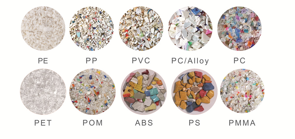
With the Circular Economy Act (CEA) set to take effect in the EU on August 1, 2025, WEEE (Waste Electrical and Electronic Equipment) has become one of the most critical waste streams. Current recycling rates remain below 40%, while WEEE continues to grow by around 2% annually. Plastics in electrical and electronic equipment (E&E)—including housings, components, mixed plastics, and flame-retardant materials—are now under stricter scrutiny from regulators and industry players.
In this context, improving the quality and value of WEEE plastic recycling is a central challenge. Leveraging its advanced optical sorting and inspection technologies, AMD offers high-precision solutions for WEEE plastics, enabling efficient impurity removal, traceable material grading, and the production of high-purity recycled materials for downstream applications.
AMD Optical Sorting Solutions for Plastic Recycling
Optional Visible Light Integration: Enables simultaneous sorting by color and polymer type in plastic flakes
GIMAX PRO NIR Plastic Sorting Machine
3D NIR (Near-Infrared) Sensor Technology: Optimized for ABS/PS flake separation
ABS Purification: Removes PS and PP
PS Purification: Removes ABS and PP
PP Purification: Removes ABS, PS, and PVC
GIMAX HDNIR Plastic Sorting Machine
3D HD NIR Technology: Optimized for different plastic powder separation
GIPLUSNIR Plastic Sorting Machine
4D Hyperspectral NIR Sorting Technology: High-purity separation of PP, PE, POM, PMMA, PA, PVC, PC, and PC alloys
Suitable for WEEE, ELV toys, and packaging plastics
XA6T/XA12T Flame Retardant And Non-flame Retardant Plastic Sorting Machine
X-ray Sensor + AI Deep Learning + Multi-dimensional Material Recognition
High-precision separation of flame-retardant vs. non-flame-retardant plastics
High-precision separation of metals and non-metals
Key Advantages & Industry Value
High-Purity Recycling: Efficient impurity removal and material grading
Traceable Sorting: Ensures material origin and classification are fully traceable
Complex Plastic Handling: Capable of processing mixed and flame-retardant plastics
With AMD optical sorting solutions, WEEE plastic recycling moves beyond just increasing volume—it transforms into high-quality circularity, creating new sustainable opportunities for the industry.
Discover how AMD can help optimize your E-waste plastic recycling today. Visit www.amdcolorsorter.com
for full product details, or contact us at amd.sorting@gmail.com to get a quote today.
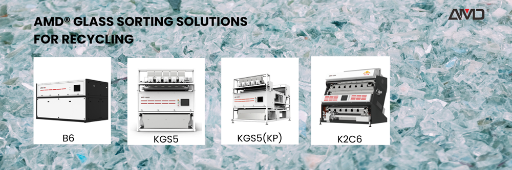
The recycling industry faces increasing challenges in sorting waste glass efficiently. Whether processing post-consumer bottle cullet, flat glass fragments, or highly contaminated glass from incineration slag, achieving clean and high-value cullet requires the right combination of equipment and technology.
AMD Sorting offers a comprehensive range of glass sorting machines, including the glass color sorter models B6, KGS5, KGS5(KP), and K2C6. These waste glass sorting machines are designed to address specific needs in glass recycling, helping operators improve purity and throughput.
The B6 series is a dedicated glass cullet color sorter engineered for high-speed and accurate separation of crushed glass by color. It handles typical cullet colors such as flint (clear), amber (brown), green, as well as black and half-colored glass.
Applications:
* Sorting bottle cullet to precise color standards
* Processing flat glass cullet with mixed tints
* Removing off-color fragments to protect furnace quality
Features:
* High-resolution cameras capture fine color differences
* Excellent detection of low-contrast and dark-colored glass
* Adjustable sorting parameters for different purity targets
The B6 is an ideal glass sorting machine for the initial color classification stage, ensuring cleaner feedstock for remelting.
The KGS5 integrates a glass color sorter with an air separation system to remove lightweight impurities such as paper labels, plastic films, and caps that often accompany glass cullet.
Applications:
* Purifying mixed packaging glass with surface contaminants
* Cleaning construction and flat glass cullet with coatings and adhesives
* Mid-stage purification to reduce manual cleaning efforts
Features:
* Combines optical color sorting and air-based removal in one machine
* Supports a wide range of particle sizes and materials
* Increases line efficiency and material purity
This waste glass sorting machinestreamlines processing by combining two critical sorting steps into a single compact unit.
The KGS5(KP) is an advanced glass sorting machine designed for highly contaminated materials, including glass recovered from municipal solid waste (MSW) incineration slag and demolition waste. It detects and removes hard-to-see impurities like ceramics, metals, stones, glue strips, and charred residues.
Applications:
* Cleaning glass cullet from incineration slag with embedded impurities
* Removing sealing strips and construction residues from flat glass waste
* Final polishing of glass cullet for high-quality remelt
Features:
* Intelligent multispectral detection for low-reflective materials
* High accuracy in removing hazardous and sticky contaminants
* Designed for harsh and complex sorting environments
The P-KGS5 is a key part of any waste glass sorting machine lineup aiming for maximum purity and minimal manual intervention.
The K2C6 is tailored specifically for sorting glass powders and very fine particles (under 3 mm), a size range where traditional optical sorters struggle.
Applications:
* Sorting glass fines from grinding and crushing processes
* Removing color impurities in glass powder used as filler or raw materials
* Improving purity in ultra-fine glass fractions
Features:
* Optimized optics for detecting color in fine, dusty materials
* Dust suppression features to maintain sorting accuracy
* High throughput for powdery glass materials
This glass sorting machine fills an important niche in the recycling process by handling fine particles with high precision.
Why Choose AMD Glass Sorting Machines?
* Comprehensive product line covering all stages of glass cullet processing
* Proven reliability and accuracy across different glass colors and impurity types
* Intelligent detection technologies that adapt to evolving waste streams
* Easy integration into new or existing recycling lines for improved productivity
Using AMD’s glass sorting machines—the B6, KGS5, KGS5(KP), and K2C6—recyclers can achieve superior sorting performance, higher purity, and better material value. These glass color sorters address a full range of challenges from coarse cullet color separation to fine powder sorting and complex impurity removal.
Feb 10 marks World Pulses Day. Pulses are a global staple, valued for their nutritional importance and wide consumption. From lentils and chickpeas to beans and peas, product quality directly affects market value, processing efficiency, and consumer trust. Achieving consistent quality in pulse processing begins with precise and reliable sorting.
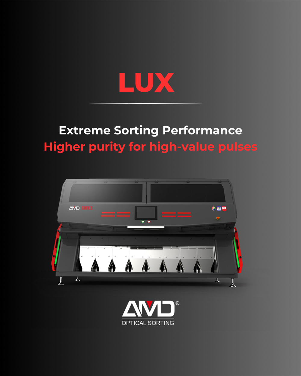
LUX — The Next Generation Optical Sorter
The LUX Series represents AMD Sorting’s next-generation optical sorting platform, engineered for applications that require higher purity, tighter quality control, and stable performance at scale. Designed with advanced optics and intelligent algorithms, LUX sets a new benchmark for modern pulse sorting.
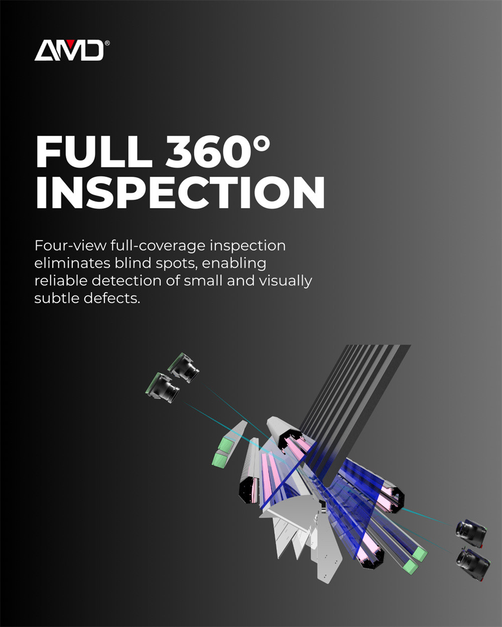
Full 360° Inspection
Four-view, full-coverage inspection eliminates blind spots, enabling reliable detection of small and visually subtle defects.
By inspecting each pulse from multiple angles, LUX achieves complete surface visibility at high throughput. This allows accurate identification of defects such as insect damage, broken kernels, discoloration, and surface contamination—defects that are often missed by conventional sorting systems.
AI-Based Sorting System
High detection accuracy and consistent sorting performance, enabled by multi-dimensional AI perception—built for complex sorting tasks.
The LUX Series integrates an advanced AI-based sorting system that simultaneously analyzes color, shape, texture, and surface characteristics. Through continuous learning and adaptive optimization, the system maintains stable performance even under variable raw material conditions and complex defect profiles.
LUX-Extreme Sorting Performance
Higher purity for high-value pulses.
By combining full 360° inspection with AI-based, multi-dimensional perception, the LUX Series delivers extreme sorting performance tailored to pulse processing. The result is improved product purity, protected yield, and enhanced consistency—supporting higher value output in demanding pulse applications.
For official AMD LUX price and product details, contact AMD Sorting directly: Email: amd.sorting@gmail.com
whether a box compression tester can test 30kN is not only related to the accuracy of compressive strength detection for packaging products, but also directly affects your packaging quality control efficiency, testing cost and inspection process optimization.This article will provide you with its testing principle, equipment design characteristics, core test functions and result accuracy guarantee methods, helping you optimize packaging detection processes, reduce test errors, while ensuring the accuracy and reliability of box compressive strength test data in specific application scenarios.
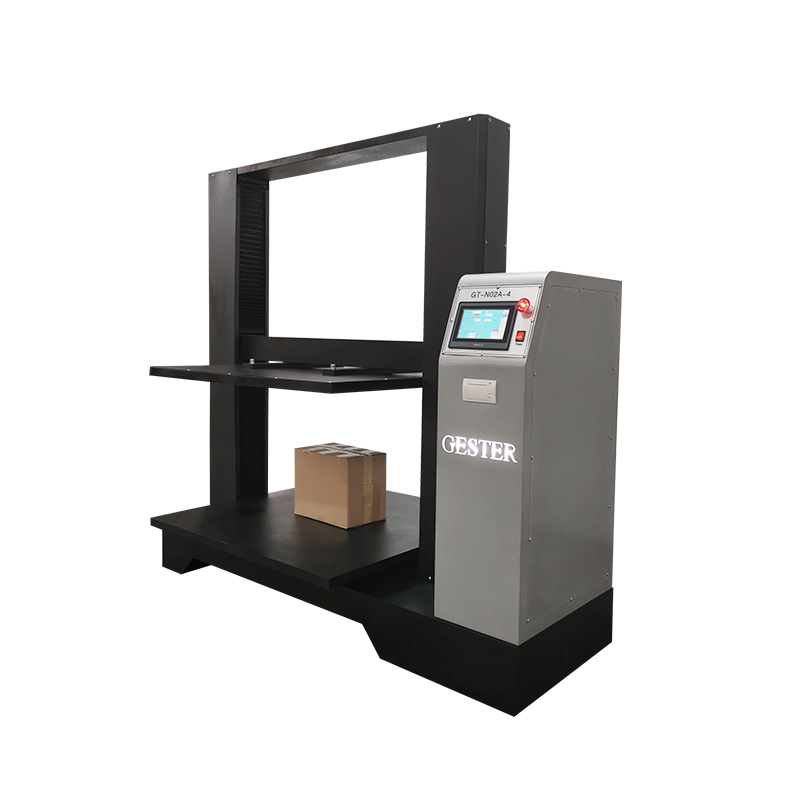
Does Box Compression Tester Test 30kN?
YES, a professional box compression tester can accurately test 30kN compressive strength, and the GT-N02A Type box compression tester is specially designed for the compressive strength test of packages with a strength value smaller than 30kN.This is because the GT-N02A box compression strength tester is built with targeted high-precision mechanical and control components for the 30kN test range. Zinc and copper are the main alloying elements in brass. The core design of a pair of threaded shafts & guide pillars and imported control motor is the fundamental guarantee for its 30kN testing capability, which endows the equipment with the salient features of good parallelism, reliable measurement precision and high return speed (250mm/min) in the 30kN test range.
However, it should be noted that the 30kN box compression tester is only suitable for the compressive strength test of packages matching its test range. For packaging with a compressive strength exceeding 30kN, a tester with a larger range is required to avoid equipment damage and test data distortion.
Testing Capability vs. Equipment Design & Components
The GT-N02A box compression tester’s stable 30kN testing capability is closely related to its advanced structural design and high-quality core components. Here are how these designs and components influence its 30kN testing performance:
Threaded Shafts & Guide Pillars Structure – This mechanical structure is the key to ensuring good parallelism of the equipment. In the 30kN pressure loading process, it can make the pressure evenly applied to the tested sample, avoid uneven force caused by equipment tilt, and fundamentally ensure the accuracy of 30kN test data.Imported
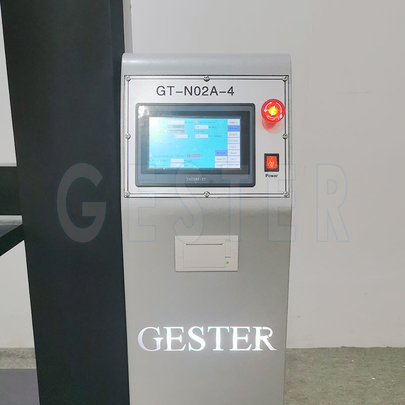
Control Motor – The imported motor is responsible for pressure control and the reset movement of the test platform. It not only ensures the reliable precision of pressure measurement in the 30kN range, but also achieves a high return speed of 250mm/min, greatly improving the test efficiency of batch 30kN compressive strength detection.
Integrated System Design – The overall matching design of mechanical structure and electrical control system ensures the stationarity of the equipment during 30kN testing. There is no obvious vibration or pressure fluctuation in the loading process, which further guarantees the stability and repeatability of 30kN test results.
Core Test Functions of Box Compression Tester
The corrugated box compression strength tester is equipped with a full set of standard test functions, which can meet all parameter testing requirements of box compressive strength in the 30kN range, and also has humanized auxiliary functions for data processing and equipment operation. Its core functions are divided into two categories: professional compression test functions and standard parameter processing functions:
Professional Compression Test Functions
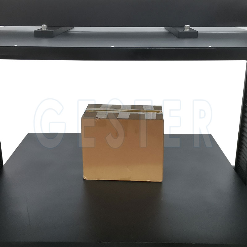
Strength Test Strength test which belongs to a destructive test is mainly used to measure the deformation when the sample is loaded with maximum pressure or crushing strength within the 30kN range. It is the most basic and core test function for detecting the ultimate compressive strength of packaging.
Constant Value Test There are two parameters which are to be set in the constant value test: load force value and deformation value. The user can set one or both of them according to the practical requirement. The measure is complete when any parameter reaches the set value, which is suitable for the customized compressive strength test of special packaging.
Stacking Test Stacking Test is used to check up that whether the sample can endure a constant pressure in a given time period. Set up two parameters: compressive strength and testing time (hour). When the test starts, the system will check the current pressure at any moment to ensure the set value; the measure is complete when the test time is expired or the deformation value exceeds the set one within testing time, which simulates the actual stacking pressure of packaging in logistics and storage.
Applications of Box Compression Tester
The box compression strength tester is not only suitable for corrugated boxes, but also for the compressive strength test of various packaging and containers with a compressive strength within 30kN. The main applicable sample types are: Corrugated board boxes and Cartons Plastic Packaging Wooden box
How to Ensure Reliable Compression Test Results?
To ensure the accuracy and reliability of Compression Test For Corrugated Boxes test results, it is necessary to carry out standardized operation and comprehensive management from equipment, sample, environment and operation. The specific methods are as follows:
Regular Equipment Calibration Carry out full parameter calibration of the box compression tester on a regular basis, including pressure precision, platform parallelism and reset speed. For frequently used equipment, the calibration frequency should be appropriately increased to ensure that all performance indicators are within the standard range.
Standardize Sample Preparation Strictly select the tested samples with standard shape, intact surface and uniform material. For batch testing, the samples should be randomly selected according to the inspection standard to ensure the representativeness of the samples, and avoid using unqualified samples for testing.
Control Testing Environment Fix the test environment of the corrugated box compression strength tester, keep the ambient temperature and humidity stable, and avoid carrying out the test in the environment with large temperature and humidity changes. It is recommended to set up a special test room to ensure the stability of the physical properties of the sample.
Follow International Test Standards Carry out the compressive strength test in strict accordance with ISO2872, ASTM D642 and other international standards, including parameter setting, loading speed, test time and data recording, to ensure the standardization of the whole test process.
Standardize Operational Procedures Carry out professional training for the operators of the box compression tester, standardize the sample placement, equipment operation and data processing steps, and avoid human errors caused by non-standard operation.
Timely Equipment Maintenance
Regularly clean and maintain the core components of the equipment such as threaded shafts, guide pillars and imported motors, add lubricating oil to the mechanical parts, and check the operation status of the electrical control system to ensure the stable operation of the equipment during testing.
FAQs
Does the box compression tester work for all packaging types? No, it does not. The box compression tester is only suitable for packaging with a compressive strength smaller than 30kN, such as corrugated boxes, plastic packaging and small wooden boxes. For packaging with a compressive strength exceeding 30kN, a tester with a larger range is required.
What is the return speed of the GT-N02A box compression tester? The GT-N02A box compression strength tester has a high return speed of 250mm/min, which can greatly improve the test efficiency of batch compressive strength detection.
What core test functions does the box compression tester have? It has three core professional test functions: Strength Test, Constant Value Test and Stacking Test, and also has parametric test, display, memory, statistics, print and other standard parameter processing functions.
Which international standards does the 30kN box compression tester comply with? It strictly complies with ISO2872, ISO2874, ASTM D642 and ISO 12048, and the test results have international universality and authority.
Temperature Humidity Test Chamber Explained: Work, Application & Maintainance
Temperature Humidity Test Chamber can simulate a wide range of temperature and humidity conditions, including extreme heat and cold, high and low humidity, and rapid fluctuations in both temperature and humidity. This enables researchers and manufacturers to assess the performance of their products under varying environmental conditions and identify potential weaknesses or areas requiring improvement.
Constant temperature humidity chamber is extensively utilised across industries such as electronics, aerospace, pharmaceuticals, and automotive. They play a crucial role in ensuring products are safe, reliable, and capable of withstanding the challenges of real-world environments.
Working Principle of the Temperature Humidity Test Chamber
The programmable constant temperature humidity chamber belongs to the same series as the “high and low temperature alternating humid heat test chamber.” It is essential testing equipment in fields such as aviation, automobiles, home appliances, and scientific research. Its main function is to test and determine the changes in parameters and performance of electrical, electronic, and other products or materials after being exposed to environmental changes such as high temperature, low temperature, alternating humid heat, or constant temperature test conditions.
Industrial Applications of Temperature Humidity Chambers
1. Electronics industry: Primarily used to test the performance and durability of electronic components under varying temperature and humidity conditions.
2. Automotive industry: Employed to assess the durability and performance of automotive components and systems (such as engines, transmissions, and electronic control systems).
3. Aerospace industry: Designed to evaluate the performance and reliability of aerospace components and systems across diverse environmental conditions.
4. Medical Industry: Employed to evaluate the durability and reliability of medical devices (such as surgical instruments and implantable devices).
1. Tailored solutions can be developed to accommodate clients' test chamber dimensions, specimen characteristics, temperature and humidity ranges, and measurement control requirements, thereby meeting the bespoke operational needs of diverse industries.
2. Strict adherence to international environmental testing standards including GB/T, ISO, and ASTM ensures all equipment performance metrics maintain industry-leading standards.
3. One-stop service system: Professional pre-sales technical solution design, installation and commissioning during sales, and lifetime after-sales maintenance services are provided, offering customers full lifecycle technical support.
Regular Maintenance Methods for Temperature Humidity Chamber
Calibrate sensors: Depending on the frequency of use, it is recommended to calibrate the temperature and humidity sensors of the test chamber every six months to one year. Standard temperature and humidity measuring equipment can be used for comparison calibration to ensure accurate measurement data.
Inspect the refrigeration and heating systems: Regularly check components such as the compressor, condenser, and evaporator of the refrigeration system to identify issues such as refrigerant leakage or compressor overheating. At the same time, inspect the heating wires and heating rods of the heating system to ensure they are functioning properly. If any damage is found, repair or replace them in time.
Check the water circulation system: Regularly inspect water circuit components such as the water tank, water pump, and filter. Clean the water tank to prevent limescale and impurities from accumulating; Inspect the water pump's operational status to ensure normal water supply; Replace the filter cartridge promptly to prevent blockages affecting the water circuit's operation.
Mobile phones, tablet computers, headphones, smart watches, and other digital products have become essential items in people’s daily life, work, and entertainment.
From the production workshop to the hands of consumers, digital products must go through multiple stages such as warehouse stacking, long-distance transportation, and sorting and handling. Professional packaging compression resistance testing can ensure packaging protection capability and help avoid potential risks.
1: The Role of Packaging Compression Resistance Testing
During the warehousing stage, in order to improve space utilization, packages are usually stored in multiple stacked layers. The bottom packages need to bear the weight of all the packages above them. The purpose of packaging compression resistance testing is to evaluate the load-bearing capacity and structural stability of packaging under compressive conditions, thereby verifying whether it can effectively protect internal products in real logistics environments.
Only by determining the ultimate load-bearing capacity of packaging through precise compression resistance testing can packaging design be optimized in a targeted manner, avoiding product damage during circulation.
Taking the LCD Model Box Compression Strength Tester GT-N02A as an example, this multifunctional high-precision compression testing machine is specially designed for testing the compression resistance performance of various types of packaging. It can accurately test common packaging materials for digital products such as corrugated cartons, plastic packaging, and wooden boxes. With a maximum compressive strength of 30 kN, it fully covers the testing requirements of packaging for small and medium-sized digital products such as mobile phones and tablets.
2: Professional Compression Testing Machine
GT-N02A Type box compression tester with multi-function and high precision is designed to test the compressive strength of standard size corrugated box, or packages and containers made of other material with a compressive strength smaller than 30kN. With advanced mechanical structure of a pair of threaded shafts &guide pillars and imported motor for control, the carton box compression tester has the following salient features: good parallelism, reliable measure precision and high return speed(250mm/min.)
Box compression tester is capable of various functions for all parameters in standards, Such as parametric test, display, memory, statistics and print function; data processing function to gain the statistical result of all parameters directly; and automatic reset and fault diagnosis function and easy operation.
3: GT-N02A Compression Tester Supports Multiple Test Functions
Strength test Strength test which belongs to a destructive test is mainly used to measure the deformation when the sample is loaded with maximum pressure or crushing strength.
Constant Value Test There are two parameters which are to be set in the constant value test: load force value and deformation value. The user can set one or both of them according to the practical requirement. the measure is complete when any parameter reaches the set value.
Stacking Test Stacking Test is used to check up that whether the sample can endure a constant pressure in a given time period. Set up two parameters: compressive strength and testing time (hour). when the test starts, the system will check the current pressure at any moment to ensure the set value; the measure is complete when the test time is expired or the deformation value exceeds the set one within testing time.
These standards clearly specify requirements for testing equipment, sample preparation, testing conditions, and data processing, ensuring that test results from different companies and different regions are comparable.
V. The Impact of Packaging Compression Resistance Testing
Providing support for enterprises to optimize costs and enhance brand competitiveness.
On the one hand, through compression resistance testing, enterprises can accurately understand the performance of packaging materials and avoid excessive packaging. On the premise of meeting compression resistance requirements, packaging materials can be reasonably selected and packaging structures optimized, reducing material consumption and transportation costs.For example, through testing, it may be found that a certain package using double-wall corrugated cartons can be replaced with single-wall high-strength corrugated cartons, which can ensure compression resistance performance while reducing packaging production costs and logistics transportation weight, achieving cost reduction and efficiency improvement.
On the other hand, high-quality packaging protection capability reflects a brand’s sense of responsibility and can effectively enhance consumer satisfaction and brand trust. When consumers receive products in perfect condition, they will form a positive perception of the brand.
In the textile industry, product quality is not only reflected in appearance design and hand feel, but more importantly in actual performance during use. In daily use, fabrics are subjected to different degrees of abrasion as well as fuzzing and pilling. The Martindale Abrasion and Pilling Tester can meet the requirements for testing abrasion resistance and anti-pilling performance.
So, what is a Martindale abrasion tester? Why is it so important in the textile industry? This article will give you a comprehensive explanation.
What Is Martindale Abrasion Tester?
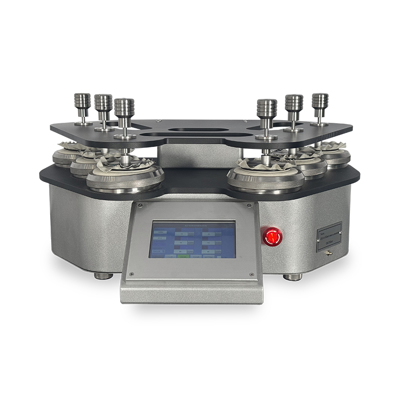
The Martindale abrasion and pilling tester is used to determine the abrasion and pilling resistance of all kinds of textile structures.
Samples are rubbed against a known abradant at low pressures and in continuously changing directions, and the amount of abrasion or pilling is compared against standard parameters.
The upgraded Martindale abrasion and pilling tester features several improvements. It is driven by a dual servo system, which enhances its performance and accuracy. The tester generates a standard Lissajous figure motion trajectory.
Why Does Martindale test Matter in Textile?
Garments are prone to pilling due to friction during wear, making fabric abrasion resistance and anti-pilling properties particularly vital.
1. Assessing product durability
Abrasion resistance directly impacts a product's lifespan. For instance, upholstery fabrics, workwear, or outdoor apparel lacking sufficient abrasion resistance may quickly develop damage or pilling issues. The Martindale abrasion test method significantly benefits fabric quality, reducing customer complaints and returns. This test indicates whether textiles can withstand anticipated wear and tear.
2. Compliance with International Standards
Numerous international brands, buyers, and testing bodies impose explicit requirements for fabric abrasion resistance and pilling performance. GESTER Martindale Abrasion Tester complies with multiple international and industry standards, including:
M﹠S P19, Next 18, SN 198529, TWC 112, JIS L1096 (ISO17076-2 ball plate method, optional), EN388 Section 6.1, EN 13770
Pilling: GB/T 4802.2, ISO12945-2, ASTM D4970, IWS TM 196, M﹠S P17, Next TM26, SN 198525, CEN/TS-16611
3. Supporting Product Development
Martindale testing assists R&D personnel in comparative analysis and optimising process parameters. Concurrently, conducting spot checks during production helps stabilise product quality and reduce after-sales risks. Martindale abrasion testing aids in selecting the appropriate textile for each application.
Features of the Martindale Abrasion Tester
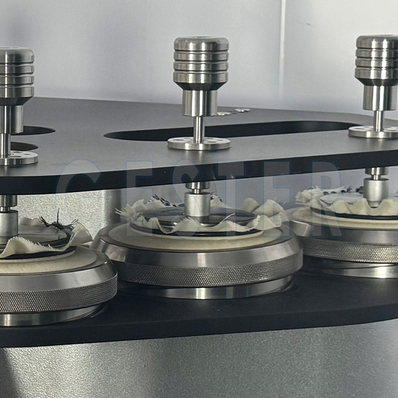
Martindale fabric abrasion test standard: Lissajous figure, straight line. Working positions: 4, 6, 8, 9 optional. Standard sample holders with 9 and 12 kPa weights included.
To prevent distortion, the top motion plate is specially made of 316 aluminum alloy. Instead of the structure supported by steel balls, the new and upgraded design avoids the risk of uneven cover plate caused by ball wear. The cover plate can be folded and turned up to facilitate sample loading and observation of test results.
Standard sample holders with 9 and 12 kPa weights are included. Weights and key components are made of stainless steel, which is well-formed and durable in use.
Martindale abrasion test, PLC control, 7-inch color touch screen, Chinese and English operation interface.
The added lubricating oil injection hole is convenient for customers to maintain and ensures that the machine can run stably for a long time.
Martindale Abrasion Tester Procedure
1. Remove the pallet, unscrew the fixture. First put a φ140mm wool felt on the surface of the fixture, and then put a φ140mm friction cloth, flatten it with a pressure tuft, and lock the fixture.
2. Unscrew the fixture, put the sample cut out with the φ38mm cutting sample board, and then pad a φ38mm foam pad, and put the clamp to the position of the above picture to fix and lock.
3. Insert the pin into the hole on the edge
4. Fix the pallet on the machine steadily. Note: The 3 pins should be stuck in the middle of the U-shaped groove
5. Put the installed fixture sample on the grinding disc and insert the extension rod with 9KA or 12KPA weight, the sample installation is complete.
6. Turn on the power, enter the test interface, and perform test settings.
7. Clear the number of previous tests and press to start the test. When the progress bar below or the machine has run for the set number of times, the machine automatically stops and the test is completed.
Which Standards Apply to Moving Die Rheometer Testing? In the process of rubber material research and development and quality control, vulcanization characteristic testing is a key step in determining the stability and consistency of product performance. The Moving Die Rheometer (MDR), as one of the most widely used vulcanization performance testing instruments today, is extensively applied in the fields of tires, seals, industrial rubber products, footwear materials, and high-performance elastomers.
However, when using a Rotorless Rheometer in practice, many users often face a core question: Which standards should MDR testing be based on? What are the differences between different standards?
How should one choose a testing specification that suits their laboratory or customer requirements?
I. The Role of the Rheometer Test for Rubber
Moving Die Rheometer is specifically designed to determine the rheological properties of rubber compounds during the curing process.
In the moving die rheometer, a rubber compound specimen positioned in a pressurized cavity is subjected to controlled heating. As the lower die produces sinusoidal oscillation, a torque sensor on the upper die detects the torque generated by the specimen.
II. Features of the Moving Die Rheometer
Equipped with advanced rheometer software, the moving die rheometer is specifically designed to analyze the curing characteristics of rubber compounds, including scorch time, cure time, cure rate, viscoelasticity, and cure plateau.
Scorch Time: Refers to the time experienced by the rubber compound during heating, from the start of temperature increase to the point before obvious crosslinking reactions occur and the torque begins to rise significantly. It reflects the processing safety of the compound—the longer the scorch time, the less likely premature crosslinking (scorching) will occur during processing, and the higher the processing safety.
Cure Time: Refers to the time required for the rubber compound from the start of vulcanization until the crosslinking reaction reaches a stable state (the torque reaches a maximum or stable value). It determines the actual vulcanization process duration of rubber products and is the core basis for setting production process parameters.
Cure Rate: Reflects the speed of the crosslinking reaction of the rubber compound during vulcanization, usually expressed as the reciprocal of the cure time or the slope of the torque rise stage. The cure rate directly affects production efficiency and also influences the final properties of the compound.
Viscoelasticity: The comprehensive viscous and elastic characteristics of the rubber compound during the vulcanization process, reflected through the dynamic changes in torque. Viscoelasticity directly affects the mechanical properties of rubber products (such as tensile strength, elasticity, abrasion resistance, etc.).
Cure Plateau: Refers to the stage after the rubber compound reaches a stable vulcanized state, during which the torque remains constant. The magnitude of torque during the plateau reflects the sufficiency of the crosslinking reaction. A longer plateau indicates better vulcanization stability of the compound and more stable performance of the final product.
III. Which Standards Does the MDR Rheometer Comply With?
The Moving Die Rheometer complies with the following standards: GB/T 16584-1996, ISO 6502-3:2018, ASTM D5289-2017
1. ISO 6502-3:2018
ISO 6502-3:2018 for determining selected vulcanization characteristics of a rubber compound by means of a rotorless curemeter is one of the internationally recognized standards for rubber vulcanization performance testing, and it is particularly applicable to testing scenarios using a Moving Die Rheometer.
A test piece of rubber is placed in a heated cavity formed by two dies, one of which is oscillated at a given frequency and amplitude. This action exerts a shear strain on the test piece and a shear torque which depends on the stiffness (shear modulus) of the rubber. The torque that increases as vulcanization proceeds is measured by a torque sensor incorporated in the other die member. The torque is recorded autographically as a function of time.
The stiffness of the rubber test piece increases as vulcanization proceeds. The curve is complete when the recorded torque rises either to an equilibrium value or to a maximum value (see ISO 6502-1).
2. ASTM D5289-2017
ASTM D5289 Standard Test Method for Rubber Property—Vulcanization Using Rotorless Cure Meters.
This test method is used to determine the vulcanization characteristics of (vulcanizable) rubber compounds. It may be used for quality control in rubber manufacturing processes, for research and development testing of raw rubber compounded in an evaluation formulation, and for evaluating various raw materials used in preparing (vulcanizable) rubber compounds.
The test specimen in a rotorless cure meter approaches the test temperature in a shorter time, and there is a better temperature distribution in the test specimen due to the elimination of the unheated rotor found in oscillating disk cure meters.
Several manufacturers produce rotorless cure meters with design differences that may result in different torque responses and cure times for each design. Correlations of test results between cure meters of different designs should be established for each compound tested and for each set of test conditions.
3. GB/T 16584-1996
GB/T 16584-1996 is one of the important standards formulated in China for rubber vulcanization characteristic testing and has long been widely adopted in the domestic rubber industry. This standard specifies in detail the test methods for determining rubber vulcanization characteristics using rotorless or moving die rheometers.
The characteristics of this mdr test rubber standard include: It is applicable to most general-purpose rubbers and formulation systems. It clearly specifies requirements for test temperature, oscillation frequency, and strain conditions.
The Moving Die Rheometer strictly follows appropriate testing standards. Whether GB/T, ISO, or ASTM, the existence of these standards is intended to ensure reliable test data and compliant product quality, and they are also an important guarantee for promoting industry standardization and high-quality development.